Sunday, August 24, 2014

3D Touch Up Painter for Unity

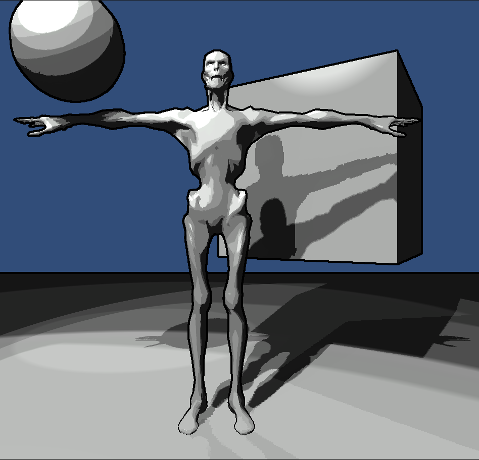
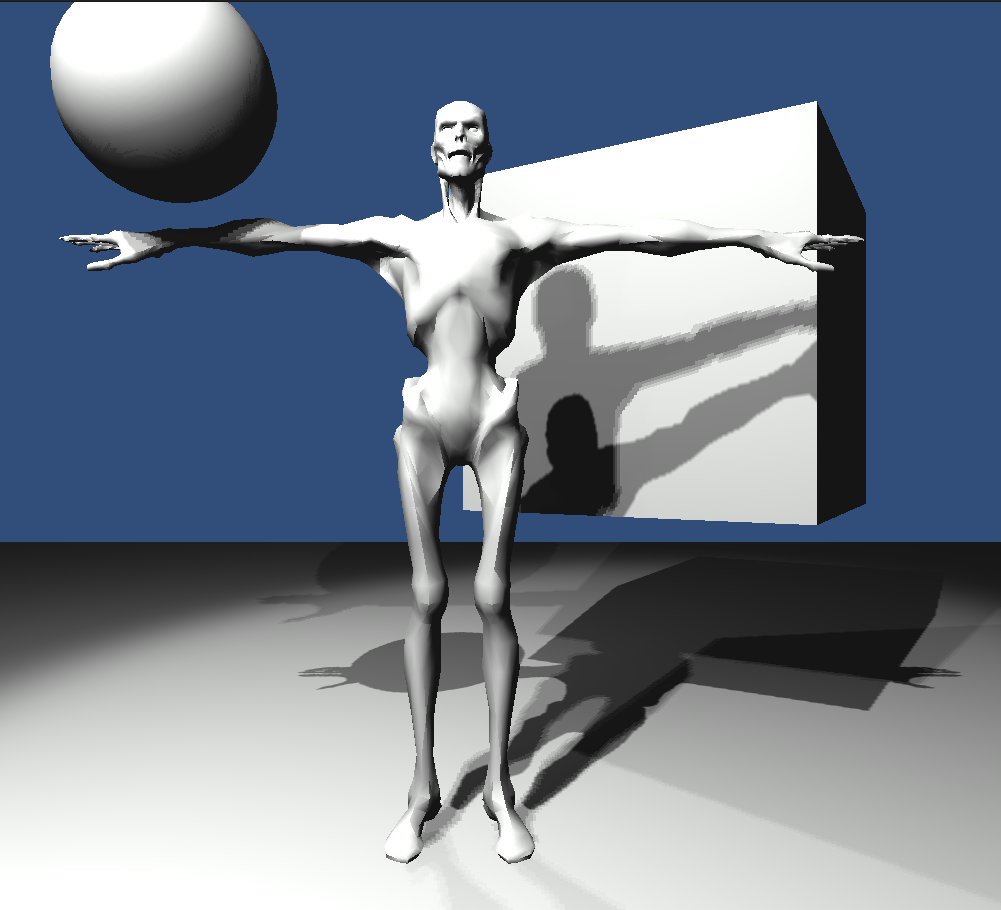
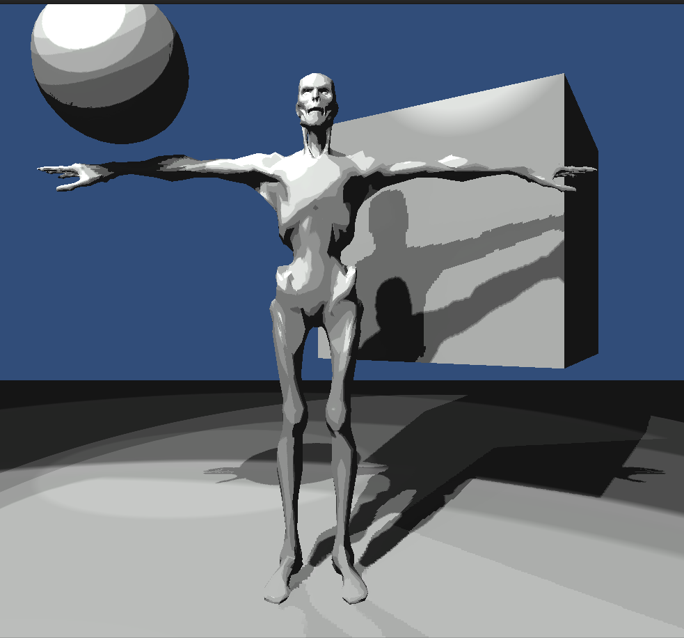
Why a 3D painting add-on for Unity?

Sometimes an artist may work on a model for hours only to discover that there's a minor error in the texture. Other times an artist may create a shader that requires weights to be inputted via vertex color to work properly. Maybe after seeing their final in game scenery they may decide that the model needs look a little more rigid or flatter.

ZBrush Polypaint
All these require that you reopen the model, texture, or both in an outside program. Do your fix, put it back in Unity to look at in the engine to see if you got it right. In particular this can happen a lot when you're using vertex color weights. In comes Unity Painter.

Unity Painter

Unity Painter will be able to easily modify the following.
  1. Vertex Color
  2. Texture Color
  3. Vertex Position
Instead of listing and explaining how painting will work I'll just provide a screen shot of the options I'm working on currently. For now I'm only worried about spherical brushes.


Good Code Follows Good Data

So far I've been doing A LOT of testing. One of my first tests was getting my brush to work just like Photoshop. This was important to me since I the artist to feel as comfortable as possible. This was surprisingly annoying. At first glance you'd think the hardness falloff would be linear.
Brush with hardness zero

However, after finding my brush working nothing like Photoshop. I dove deeper and wrote a small program to help me find out what the falloff is. The graph below shows a single color channel go from zero to one as you increase your distance from the center of the brush. As you can see this falloff is not linear, or cubic splined, or even cos interpolated. Instead it follows a natural log falloff that has uses a Perlin smooth step function to smooth it out.

Perlin Smoothed Natural Log Interpolation
Other preliminary tests have shown some other Photoshop weirdness. Such as,
  1. The Photoshop brush GUI gizmo will decrease in size by as much as 80% at zero hardness.
  2. Photoshop will increase its draw radius by as much as 55% at zero hardness.

Start At The End - UV Space to World Space

It's not hard to check whether or not a point is inside a sphere. Therefore its trivial to check whether or not a model's vertex lies inside a spherical brush. However, what about a UV space pixel on a texture? How do I find whether or not I should draw to a pixel on my texture when I'm painting in world space? My basic method is the following with adjustments needing to be made if the model is not in the same pose as it was unwrapped in.
  1. For each triangle find the pixels that it covers in UV space.
  2. For each triangle create a texture to world space matrix and find each pixel's world space coordinates
  3. Create a new data structure of world space positions for each texture pixel.
  4. For each brush stroke use the new data structure to find out which pixel is inside the sphere.

Step 1

We can use Unity's Mesh class to find the mesh's triangles, the triangles vertices, and the vertices corresponding UV. From here you can use barycentric coordinates to test out if your pixel in UV space lies inside the triangle. Click to find out more.

Step 2

We can also use the UV points for each triangle vertex to construct the following UV space triangle equation \[P_{t} = P_{0} + su + tv \,\, for \, s \geq 0,  \, t \geq 0, \,  s + t \leq 1\] \[and\] \[u = P_{1} - P_{0}\] \[v = P_{2} - P_{0}\]

For my method we need to find the weights s and t. Note that \(P_{t} = (x,y) \) and therefore we can say \[x = su_{x} + tv_{x}\] \[y = su_{y} + tv_{y}\] Using the \(x\) and \(y\) components of \(u\) and \(v\) this allows us to construct the following matrix that when reduced will yield us \(s\) and \(t\).
Reduce the matrix to echelon form.

Now in this form it is clear that a new matrix can be constructed from our \(s\) and \(t\). This new matrix allows us to calculate the weights of any pixel that lies in our triangle given its UV coordinates.
The weights \(s\) and \(t\) are important since the weights for the pixel will not change for the triangle even when the triangle in in world space! Assuming that the model is still in its original pose. That means that to calculate the pixel's world space coordinates all we have to do is recalculate the triangle equation using the vertice's world space points, apply the weights for that pixel, and done, you know have its world space point.

Step 3 and 4

Since a texture is just an array we can store each world space position in an an array of equal size and dimension.

The quick and dirty way to do step 4 is to just check every pixel if its inside our spherical brush but this can be painstakingly slow for large textures. Instead we can examine which triangles intersect or lie inside our sphere and then test out only the pixels that belong to those triangles. 

Concerns

I've already spoke about how the model essentially can't be in the middle of an animation. It needs to be in its original pose since I don't take into account it's bone blend weights.

My second concern has to do with bad unwraps. A bad unwrap can cause textures to be pulled, stretched or squeezed. This happens when the UV triangle doesn't match the ratio's of the model triangle. I haven't fully tested this algorithm out yet but I believe this problem to be purely an unwrap one. If it does end up being a major problem, back to the drawing board.

Ninja edit: I realized on my way to work this morning that it may not be too hard to construct a texel to world space matrix that accounts for triangle ratio changes when you assume the texture lies on the same plane as the triangle.

Roadkill showing texture deformation due to unwrapping

Till next time...

I hope to have this done or mostly done by the next time I post. I'll be sure to post anything interesting I find along the way. In particular I want to write a little more about how to use Unity's Editor.OnPreviewGUI() since there is literally nothing useful out there on it. It's own example throws an error. I've had to use the C# Reflector to figure it out so I'll be writing about that too.

Tuesday, June 17, 2014

Stylized Deferred Rendering In Unity

Deferred Toon Shading And Sobel Edge Detection In Unity

Final Result

Deferred Rendering Comes With An Artistic Cost.

Unity comes with a deferred rendering option that comes with a lot of perks. The biggest being...
  1. More than one light source can cast shadows.
  2. Spotlights and point lights can also cast shadows now.
  3. General efficiency in rendering scenes.
However, due to the way deferred works you can only apply one lighting algorithm to all the deferred rendered objects in your scene. You can still use more than one lighting algorithm but those objects will be forward rendered.

Unfortunately Unity doesn't give you an easy way to change the deferred lighting algorithm it's using. Below I'll show you the steps you need to create a simple deferred toon renderer in Unity.

Custom Deferred Toon Shading in Unity

No Toon Shading or Outlines
  1. Download Unity's built in shaders that corresponds with YOUR version of Unity. Having the correct version is very important or else you might get errors when you try to compile.
  2. Under the DefaultResources folder drag and drop the 'Internal-PrePassLighting.shader' file into your Unity project's Resources (make one if you don't have one) folder and restart Unity. It's important to place it in your resource folder or else it won't be there when you try to build.
  3. Open up Internal-PrePassLighting.shader and edit the CalculateLight function to use whatever lighting algorithm you want. In my case I made two changes. I added the following property. 
    _LightRamp("_LightRamp",2D) = "" {}
  4. Removed this Line inside of the CalculateLight function (it calculates the diffuse lighting).
    res.xyz = _LightColor.rgb * (diff * atten);
    and replace it with
    res.xyz = _LightColor.rgb * tex2D(_LightRamp,half2(diff*atten,.5)).rgb;
  5. That's it. Save and you're done with the Internal-PrePassLighting.shader file. 
At this point you'll see all white since your not using a ramp.
I used the following.
There is some white at the end.
Import a ramp texture into unity. Make sure to go to texture properties and do the following.
  1. Set the texture type to 'Advanced'.
  2. Uncheck mip mapping.
  3. Set the wrap mode to clamp.
 Finally just drag and drop the ramp texture into your Internal-PrePassLighting.shader file's default _LightRamp texture property and apply. You can also do this with Shader.SetGlobal() function.

Borderlands Type Post Process For Outlines

Outlines created by the Sobel post process effect

No Outlines

Final Composite.
UDK has a great (and lengthy) tutorial on creating a Sobel Edge Detection Shader on their website. I basically just followed their tutorial but made it work in Unity. You can download the package here and take a look. To use it just select your camera. Under the menus select Component/Image Effects/Sobel. You'll probably then need to customize the values used.

Monday, April 7, 2014

Swipe Game - Level Creation Tool

Creating a Line Using Triangles

My Level Creation Tool

Sometimes it's better to start over

Originally I had a tool that just intelligently recorded points I drew using using my tablet. So I started out by just wanting to take these points and create a line that goes through them. However, due to geometry you can get some very weird corners if you're not careful. Those can be seen in the above video. So I opted to rewrite my level creation tool in order to know what my line will look like while I'm creating it.

Imagine a line going through the the center of the above line. The only points that matter are the end points and corner points. I call these points center points. If you place vertices evenly on either side of the center points you get the above line. It's ugly. You can remedy this by adding more center points and vertices around those center points. However, I'm running on mobile. I want as little vertices as possible. Below I'll go over how to do this and make it look right. The only downside to this is that you can get very long corners.

Calculating Vertex placement

Well this is messy now isn't it

Problem

Given the above points how do we find where to place vertices \(V_{1} \) and \(V_{2} \). i.e. How do we find the length of the hypotenuse \(H \) of the above triangle.

Finding a width

So before my Technical writing professor begins to chew me out for the above diagram let me at least explain it. If you remember trig then for our case \[\cos \theta = \frac{W}{H}\] or by rearranging the equation we get \[H = W* \sec \theta\] We can find \( \theta \) by using the dot product. Its easy to calculate the unit vectors \( \hat{A} \) and \( \hat{B} \) given \( P_{1} \), \(P_{2} \), \( P_{3} \). Note, I forgot to give \( A \) and \( B \) their hats in the picture
So then \[ 2 \phi = \arccos (\hat{A} \cdot \hat{B}) \] and \[ \theta = 180 - \phi \]
This could probably all be optimized using some quick trig magic (identities).
Note if \( \theta = 90 \) degrees then \( \sec \theta \) will fail when calculating \(H = W* \sec \theta\) . You need to make a special case for this and make \( H = W \) in case this happens.

Placing the vertices

The last part involves adding the unit vectors \( \hat{A} \) and \( \hat{B} \) to get \( \hat{C} \) (normalize the sum to get \( \hat{C} \) ). \( \hat{C} \) lies exactly between \( \hat{A} \) and \( \hat{B} \) only because they are unit vectors. From there you just move \(P_{2} \) in the direction of \( \frac{H}{2} * \hat{C} \). ie \[ V_{1} = P_{2} + \frac{H}{2} * \hat{C} \] and \[ V_{2} = P_{2} - \frac{H}{2} * \hat{C} \]

A quick comment on triangles

If my next point \( P_{4} \) where to create an angle in the opposite direction of \( \hat{C} \) then my new vertices would be moved in the opposite direction of the vertices previously laid out. This can screw up your triangles when you're creating them. Using the dot product to make sure this doesn't happen can be helpful.

Final Thoughts

This is a tool that runs on my computer so I'm not concerned about how it runs on mobile but next time I might write on how we can shrink/edit the lines quickly on mobile.

Edit: Got Latex to work. WOOO!

Monday, March 24, 2014

Swipes of Fury I

Playtesting at GDC 2014

I went to GDC expo this year. There was lots of interesting emerging tech. The new Unreal Engine is going to be available with a monthly payment. I tried out the Virtuex Omni. It has a lot of potential once they work out the kinks. I could probably have a whole post on just what I saw at GDC but thats not what this blog is about! So instead here's a video of the mobile game I'm currently working on. Swipes of Fury (name pending).

Game State

The state of the game isn't too bad right now as you can see but it still requires some additional VFX and audio to really help the game feel complete. The GUI looks ok in this video but once its thrown on my Dad's Galaxy S4 with an HD screen the GUI becomes so small its basically unreadable. It has about eight total levels right now but I'm going to aim for 50+ since the level building tool I made for it is pretty easy to use.

Feedback

Feedback was overall positive. People loved swiping and getting that cool wave effect BUT the biggest issue was that the players didn't know when they fell off the track and where the start of the swipe was.

Resolving Feedback issues

In order to resolve the biggest issue stated above I've decided to throw away my awful looking arrows and write my own 2D line renderer optimized for this games use. Unity's is no good in this case for two reasons. The first is the obvious overhead in the ways its used. It requires all the points ahead of time and to remove point you need to feed it a whole new list of points. The second is in the way it deals with sharp angles. It tends to focus all the corner points in at a single point creating a steep ugly looking angle. I'll be posting a more detailed post about this later. Below are the things I'll be working on.
  1. Optimized 2D line Renderer
  2. FX and Audio Messenger System
  3. General VFX
  4. Level Design
  5. Audio Design
  6. Rating System
  7. Get iOS to like me

Wednesday, February 26, 2014

Making A Game...

...Always Starts With A Cool Toy


A toy for a game

Me and a former class mate have decided to make a game to release on Google Play. So far we are on the toy building stage. This is a toy that I came up with that's just fun to play with.

But what is it?

It's just a series of water droplets reacting on a mesh. A few years ago I read this book that I think implements this paper. The original paper talks about its implementation in Cinema 4D but with today's PCs it is possible to implement it in real time as long as the mesh is small. Currently its implemented in Unity for PC but with a few tweaks I'm 98% sure it can run on mobile easily. The way it's working right now is that height values are given to the shader through the UV2 coords and used to sample a ramp texture.

Saturday, January 25, 2014

Burning Ashes

Ashes! Ashes! We all fall down!

Inspiration

Typically in a high heat situation you see a lot of embers buzzing around. Sometimes if the material that is being lit is very light i.e. paper, leaves, volcanic ash, etc will take to the air before it's fully lit. I've made plenty of embers before but I wanted to try to replicate this effect in UDK. As an extra challenge I didn't want to allow myself to use alpha cutout plug.

Shader Overview


Entire Burning Particles Shader

Three Parts

I wanted to have a texture that was going to be slowly eaten away by heat. To me that meant having three parts to the texture. An unscathed portion that heat hasn't gotten to yet, a burning portion that is still hot, and finally a burned portion that has already burned off.

Burn Erosion

Burn Erosion Portion
Alpha Erosion typically makes materials transparent at different rates with less opaque parts fading out completely first. However, it still makes the entire material fade proportionally. This means that even places that haven't been burned yet would became less opaque. Not what I want.

My solution to this was using an if statement. If my [Texture Value - Opacty Value < Opacity Value] then those pixels were given an eroded (tex val - opacity val) value other wise the pixels were unchanged. It's a little confusing in the shader since i do a 1 minus operation to make both sides of my comparison increasing or decreasing at the same time. Without the one minus the if statement would always be false (Yes, this can be further cleaned up).

The rotator above is just to give some more randomness to the particles along with the standard contrast and brightness adjustments. I also added an inversion option at the end.

Colorizing

Color Mask
So that covers what pixels I decide to erode away. Some pixels will be zero i.e. fully transparent. Those values are fed into the opacity input. That leaves us with two parts left, the burning portion and unscathed portion.

I invert the output from my burn erosion to create a mask. Originally the parts that were completely opaque had a value of one but once I invert them they go to zero. This allows me to add in to those zero parts the value of my texture sample. I colorize the remainder of the mask by multiplying by my vertex color. This gives us our two remaining parts of the embers.

That other arrow you see going into a multiply is to make the burning portion flicker. It's a trick I learned from one of Bill Klidas's tutorials. It's a hack but gives you an easy way to make it appear as if the embers are flickering randomly

Flickering
Its basically adding sin and cos together then finding the abs value. Then I just threw in an add (that's set to .2) so that I could never have a value under .2. The time multiply at the end uses a dynamic parameter to change the flickering rate.

Friday, January 3, 2014

Demo Reel 2013

Demo Reel 2013


What have I been up to?

This reel has a compilation of everything I've done for about the last year that I wanted to show off. It has two different games that I worked on along with some random effects I worked on both real time and pre rendered. And in case you are wondering the music is Jelly Castle (Orchestral Mix) by MDK available free from creative commons.

Audio Wave

This is a game me and my friend Evan Li worked on for our game design class. He did all the game play programming while I worked on the effects and artwork. It's a music based game where you have to click the hexagons in rhythm to the music. Originally the mesh moved much like dropping something into water. but after some playing around it didn't really have the right look or feel. So instead I opted to use the normal information provided originally to sample a ramp texture.

Rule the Tides

This is what I worked on for my last and final semester at The Entertainment Technology Center. I had to split my time between doing game play and UI programming as well as doing effects. The VFX had to be optimized to work on Ipad so instead of using fancy shaders to do the work dynamically I prototyped most of the materials in UDK or Maya then used Maya, After Effects, and Photoshop to create flip books. I had a lot less dynamic variation this way but since most of the effects took place far away color blocking was more important than fine detail.